Due to the substantial improvements in LED technology over the years, this ancient (2005) project is outdated. High voltage Xenon flash tube based strobe lights are simply not relevant in DIY applications any more when one can now purchase LED modules really cheaply that are actually a lot brighter than tube used in this project!
This article has been archived here due to its ongoing popularity – when I took it down, I was asked to repost it within a week!
What is it?
The beat triggered strobe light creates a bright, white flash up to 5 times per second to the beat of your music.
Why I designed it
Having previously constructed a simple strobe light that flashes periodically by virtue of it’s own internal oscillator (with variable frequency from about 0.5 to 12 Hz), I found myself attempting to synchronize the flashes with the recurring beat of some music. This gave me the idea of developing a beat triggered strobe light. The project is presented here.
Circuit Overview
The circuitry isolates just the main beats from a song, typically from a kick drum by sending audio from a microphone through a second order low pass filter. By comparing the resulting low frequency part of the audio to a reference level, just the peaks (the thuds of the kick drum) are detected. A link at the bottom of this page will take you to a high resolution full schematic but for the purposes of explaining circuit operation, I have broken it up into 4 pieces.
Beat detection circuitry
Looking at figure 1 below, it can be seen that one of the two amplifiers inside a LM358 operational amplifier is used to amplify the signal from a small electret microphone to a more usable level. From here, a 6.25mm Jack socket allows the insertion of a line level signal instead of the microphone for better results. If a line output from the audio source is available, it should be connected here. If not, the internal switch inside the socket will connect the amplified microphone signal. From here, a simple low pass filter is formed by R3 and C10, with a cutoff frequency of 159Hz. The other amplifier in the LM358 package is used to amplify this signal before feeding it into another low pass filter consisting of R5 and C11, also 159Hz.. The gain of this amplifier is adjustable by varying the potentiometer R24. This allows the level to be set. In practice, once set, this does not need too much fiddling if the volume of the sound system remains constant. It is essentially an adjustment to suit the volume of the party. 😀
Pulse shaping and flash rate limiting
The next section of the strobe circuit is the pulse shaping section. It is shown in figure 2 below. To prevent multiple triggering and also to limit the maximum flash rate, a one-shot timer is used. The timer is configured so that once triggering has occurred, it must complete before another trigger action can occur. This is done by the way of U2B which prevents U3, a 555 timer from retriggering unless it has finished the previous trigger operation. The result is that the output of U3 goes high when a flash is desired and remains high for a duration of around 200mS to prevent further flashes. C4, R16, D1 and U2C form an edge detector, to sense when the output of U3 makes a transition from low to high. When this transistion occurs, a very brief pulse is created to fire the flashtube via the opto-coupler. This is achieved by rapidly charging C4 via R16 and monitoring the voltage drop across R16. When the output of U3 goes low again, C4 discharges through D1. This happens even faster than the charge operation as C4 must be ready to receive the next flash as soon as possible. Although D1 causes C4 to discharge very quickly by providing a low impedance path for current to flow from ground, a charge pump effect occurs where the positive terminal of C4 is pulled to ground by U3, causing its negative terminal to go to about -12V! D1 ensures that it cannot go below -0.7 volts, but alas, this is still well outside the valid input range of U2C, which needs to make a decision about whether the pulse is occurring or not. To solve this issue, R27 and R28 form a voltage divider to keep the inputs to U2C well above zero for predictable and reliable operation.
The reason for limiting the flash rate of the strobe is so as to avoid exceeding the manufacturer’s power rating. The tube used is supposed to be rated at 5 Watts. Therefore, if I give it a 1 Joule flash, I can perform no more than 5 flashes per second. In practice, it was found that the maximum flash rate was closer to 7 Hz. This should not be a problem because, unless the sensitivity is so high that the flash rate limiting is always occurring, the strobe will be flashing in time with the music, which should be less than 5 Hz. (5 Hz translates to 300 beats per minute. Even most fast techno music will not get close to this!) More on the tube later.
High voltage flash system
The high voltage section is actually the simplest in the beat triggered strobe. Thus, if you were able to get the two low voltage stages operating correctly, then with appropriate care, you should have no difficulty with the high voltage section. Having said that, appropriate care is vitally important as this is more dangerous than your average mains project. The reason for this is that not only are we rectifying and smoothing the mains, creating a powerful (lethal!) DC bus of 325V, but we also generate pulses of almost 2000V! Thus, please read the warning below and if you are in any way unsure, GET SOMEBODY TO HELP YOU!
Warning:
This section of the strobe contains mains voltages, a high voltage dc bus of over 300 volts and generates pulses of several thousand volts! All of these have the ability to KILL you. As little as 30mA can be fatal. These voltages are sufficient to cause several times this current to flow through your body! DO NOT attempt construction unless you have mains voltage experience. I take NO responsibility for any injury or loss direct or otherwise from this circuit design. I also take no responsibility for any errors or omissions in the design. If you cannot judge whether or not my design is safe then you should not be building it full stop! Having said that, if properly constructed, this strobe is a very cool project that can be operated safely by anybody once built.
By reading on, you agree to the above conditions.
The schematic for the high voltage section is shown in figure 3 below. The mains is full wave rectified. Unfortunately I had problems when using filtering so a 120 volt version that uses a voltage doubler is not possible because of this. I found with capacitors across the output of the bridge that the tube sometimes did not extinguish properly and glowed dimly continuously! I may look into the possibility of a 120 volt version in future, but apart from the voltage doubler circuit, I see no way that would be testable in my exclusively 230 volt country without a variac (which I do not own). R25 and R26 limit the charging current of C7 to reduce stress on this critical component. The power dissipation in these resistors should be no more than about 3 watts by my calculations, but to be safe, use 5 watt resistors as the short circuit current (during the very brief flash) will cause a peak dissipation of just below 10 watts. From here, a 325 volt dc bus is created. This powers the flash tube which when fired rapidly discharges C7. This is not good for C7, however, I have yet to have an electrolytic or flash tube fail in either of my strobes. The only failure I have had has been an SCR and I have since used much larger SCRs as they are not much more expensive. R21 and R22 form a voltage divider and charge C15 to around 65 volts. When the opto-isolator is triggered by the low voltage circuitry, Q1 is triggered and the energy in C15 is dumped into T1. T1 has a ratio of 1:30 and steps this up to around 2000 volts. This high voltage is applied to the middle terminal of the flash tube which goes to a silver coating on the surface of the glass. This high voltage pulse ionizes the xenon gas inside the tube, causing an arc to occur inside, rapidly discharging C7 in a bright white flash. When the voltage across the tube falls too low, the arc is extinguished. C7 then recharges. The lack of filtering of the rectified mains ensures extinguishing occurs reliably as the values of R25 & R26 are not sufficiently high to ensure this. They need to be relatively low to ensure recharging in time for the next flash. That’s really all there is to it. Be aware that the wire from T1 to the flash tube’s centre terminal carries several thousand volts and must be well insulated. Leads to the tube should all be as short as possible. I have found that 30cm (12”) of 3 core mains appliance cable works quite happily so this is not too crucial but be sure that nothing can short.
Flash tube details
The flash tube I used is available from several local electronics hobby shops. www.globalpc.co.nz sell the tube as S4040 and the matching trigger transformer T1 as M0104. www.jaycar.co.nz sells the same tube as SL2692 and the trigger transformer as MM2520. Have a look at your local electronics supplier’s website. Unfortunately I cannot find an equivalent flashtube at the time of writing on the Farnell or RS websites which is a pity as they are more geared for international sales. Xenon is generally a pretty good search term to start with. The flashtube I used is shown in figure 4 below. The tube is approximately 4cm from the glass tip to where the terminals protrude and about 7mm in diameter.
Once you have located a suitable flash tube & trigger transformer, you will need to calculate values for C7 and R25 & R26. We start with C7. Divide the maximum power by the maximum flash rate e.g. 5 watts / 5 Hz = 1 Joule per flash. Then we use the capacitor energy equation to calculate capacitor size. The energy stored in a capacitor is E = CV^2 so dividing the energy per flash by the voltage squared gives the desired capacitance. The peak voltage is the square root of 2 times the r.m.s. mains voltage i.e. 1.414 x 230 = 325V. So for 1 Joule per flash I get an answer of 9.5uF so have used the common nearby value of 10uF. The slight increase should not be a problem. Next the resistor values are calculated. I have used 2 to spread out the power dissipation so they will most likely have the same values as each other. The total resistance needs to limit the current as much as possible but allow the capacitor to charge in time for the next flash. 3 time constants works pretty well so take 1 divided by the flash rate to get the charge time. For a rate of 5 Hz I get 200mS. If this is 3 time constants the time constant must be this divided by 3 i.e. 200mS/3=67mS. T=RC and we know C so R=T/C which for me is 0.067/0.00001=6667 ohms. I have used two 3300 ohm resistors in series which is close enough. Working out what power rating to give the resistors is a lot harder, involving integrals of exponentials. I worked out the R.M.S. current and squared this and multiplied it by the resistance to get an idea of the long term dissipation. I also worked out the average power. Both of these were ignoring the flash, assuming that it had a duration of zero (not true). These both gave about 3 watts. Then I went for an exaggerated worst case scenario –the flash is continuous and the full 230 volt mains appears across the resistors. 230×230/6600 = 8 watts in my case so two 5 watt resistors provided 100% reassurance of safety.
Opto-coupler selection
Added April 2009
For safety, the low voltage beat detection circuitry, whose sensitivity pot, line input jack and possibly internal microphone can come into contact with a human, these MUST be isolated from the mains. The low voltage power supply will be explained shortly, but the drive signal to set off a flash is the biggest challenge. To overcome this, we use an opto-isolator which you are probably aware consists of an led and a light dependant transistor to get the signal across without direct electrical connection. The type of opto used is unimportant, so long as it meets the minimum safety requirements. Because the mains voltage can fluctuate, it is entirely possible for the rectified mains voltage across C7 to be as high as high as 370Vdc. Thus, the most that the opto will have to block, thanks to voltage divider R21 & R22 will be 76V. Therefore, with some safety margin, you can use any opto with a voltage rating that is at least say 80V. The other consideration is the current that the opto can carry. At 76V, R20 will limit the current flow to less than 40mA. I used a H11D1 opto as it has a massive 300V breakdown on its transistor. The third issue is the isolation between the low voltage circuitry on the diode side and the mains wiring on the transistor side. Both the H11D1 and H11D2 have over 1000V of isolation which is sufficient to ensure safety. Unfortunately not many retailers have a very wide range of opto-isolators so you may have to shop around. I have found that South Island Component Centre in Christchurch have a very wide range of opto-isolators including the H11D2 so if you are in New Zealand that is a good option. They also have good prices on presensitised photoresist pcb boards if you wish to photographically etch a board for the strobe as I did. As long as it has at least 1000V isolation from diode to transistor, 40mA continuous collector current and 80V collector-emitter blocking voltage, any pin compatible opto-isolator will do.
Low voltage power supply
The low voltage power supply is very simple. A schematic diagram of the on board sections is shown in figure 5 below. An “off board” transformer steps down the mains to a safe voltage which is rectified and smoothed to give around 16 volts dc. (I used a 16 volt DC plugpack or “wall wart” I had lying around). In the final PCB I should probably include space for a bridge and large cap so that AC plugpacks and straight transformers can be used too. The supply is then fed through a linear regulator to create a reasonably quiet 12 volt bus for the electronics to operate from. D4, R32 and C20 form an additional filter to provide an extra quiet power supply to the microphone amplifying circuitry. R30 and R31 form a voltage divider to provide a half supply reference for audio signals to be centred around as the system runs from a single ended supply.
Construction
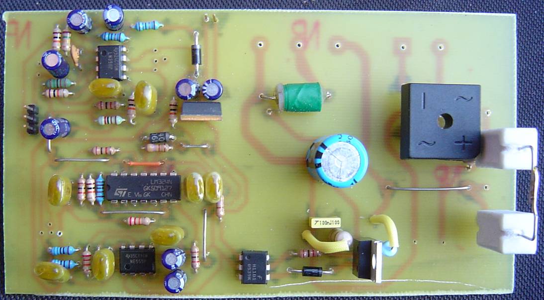
To minimise the chances of an error, short circuit or other catastrophic failure, I suggest assembling the strobe on a printed circuit board. I designed a circuit board for the strobe and it worked very well. There were a few minor errors, such as a missing ground trace to the LM358 and R27 & R28, were missing entirely. Apart from that and a few extra pads, it is a very good board with plenty of clearance between high voltage traces. I intend to fix the few minor issues with the current layout and upload it for you to use, free of charge to etch your own boards. If you contact me by email I may also be willing to send you a board for a fee. If it is late January 2008 and I still haven’t uploaded a PCB layout, feel free to nag me. The board in it’s prototype stage is shown in figure 6 below. If you are up to this stage, I reccomend connecting an L.E.D. in place of the opto-coupler. This will allow the low voltage circuitry to be fully tested without the hazard of having dangerous voltages on the board. Having done this, connect the off-board pot, the microphone and place a jumper across the lower 2 pins of the 3 at the left of the board. Apply only the low voltage dc power rail of 12 volts. Adjust the pot & trimpot. You should be able to get the L.E.D. to flash when you bang the table and if well adjusted (particularly the trimpot) you should be able to wind up the pot and get it going with the beat of some moderately loud music. Winding it down should prevent erroneous triggering on loud music. The strobe works particularly well if you have a subwoofer. 😉 You can now install the jack socket. The top pin at the left of figure 6 is ground, the bottom is the input which must connect with an inserted jack plug and the middle pin must go to the switch connector on the jack socket so that it connects to the bottom pin when no plug is inserted. If all is well, the L.E.D. can be removed and the optocoupler inserted.
High Voltage Wiring
Wiring of the “off board” components is probably the area where it is easiest to make mistakes, which is why I tried to keep as much as possible on the board. Even so, be very careful and triple check all work! Basically, we take the incoming mains, provide an appropriate cable restraint and then connect to a switch. The switch may only switch the phase line, or it may also switch the neutral line. Either way, a switch rated for at least 1A and 250V AC is required. Incidentally, the terminology seems to vary from country to country but when I say phase in reference to a particular mains connection, I am referring to the live/active/one that has 230V with respect to earth etc as opposed to neutral or earth. From the switch, phase is connected to a fuse. This is a 0.5A 250V fast blow fuse. You can use whatever size fuse (and matching holder) you can get your hands on, as long as it is rated for the mains i.e. 250V AC. 3AG and M205 are popular sizes. From here, the neutral & phase are connected to the circuit board. This can be used as a junction point to take switched & fused phase & neutral to the transformer that is to power the circuitry. I used a plugpack/”wall wart” which has a built in rectifier and filter capacitor to convert its low voltage output to DC but intend to include room for these components on the final pcb layout so that a straight unenclosed transformer may be used. We need about 15V DC and no more than about 25. To translate the DC voltage to an AC voltage that can be rectified and smoothed to create it, we divide by the square root of 2 i.e. 1.414 thus we need a 12V or 15V AC transformer or any DC plugpack in the range of 15-25V. I personally had a plugpack lying around that was rated at 16V DC at up to 300mA. The circuit should not draw more than around 100mA. I used an extension cord as my cable & plug because this is cheaper (mass produced guess where) than buying a plug and some cable separately. It also meant I could have an extra long cord on the strobe (very handy!) and a free socket to plug the plugpack into!
We then connect the flashtube to the PCB. There are 3 wires. The terminals on either end of the flashtube may look identical but on some tubes they don’t. If both just poke a wire into the glass, it doesn’t matter but if they are different, you need to connect the positive to the end with the black swirly thing and the negative to the other end for best life expectancy. (I have no idea how else to describe it, see figure 4). I have found that 3 core mains cable over a length of 25cm works fine for this. (Use some of that extension cord I mentioned 😉 )
Housing
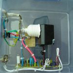
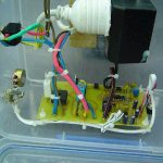
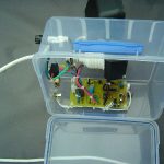
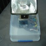
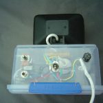
You can house the strobe in just about anything that is strong and sturdy. I suggest plastic as it insulates and is less likely to cut one’s fingers with sharp edges like metal. If you do use a metal enclosure you MUST earth the case securely. Use a proper crimped or soldered lug and screw this to the case (after roughening the metal with sandpaper) with a spring washer & two nuts. The second nut prevents the first from coming undone from vibrations. I chose to use a plastic case. Bear in mind that your flash tube needs to be placed behind a transparent glass or perspex cover. A reflector is highly recommended. I stumbled across a clearance car fog lamp which provided the ultimate housing. A thick high temperature plastic casing with a strong glass front, containing a 60W halogen bulb. All I had to do was remove the bulb & holder and enlarge the hole. The flash tube fitted nicely and I was able to secure it using terminal blocks. Make sure that the wires don’t touch the reflector though as some reflectors are made of metal. Heatshrink tubing is brilliant although if you’re worried about damaging the tube when heating the tubing, try spaghetti tubing (awful stuff) or else insulation from some Cat5 or other cable. I would then heatshrink over the non-tube end of this to stop it sliding. Figure 7 shows my completed strobe light from various angles. When mounting the PCB, you should be using nylon screws, nuts, spacers etc. This ensures that if anything comes undone, it does not pose an electrical hazard because it is non-conductive. You also need to cable tie the wires not just for neatness but to ensure that if anything comes unsoldered or otherwise disconnected, it cannot travel far enough to touch anything else. A knob for the pot is a nice finishing touch and provides additional (although theoretically unnecessary) isolation from the person touching it.
Construction Files
UPDATED 25 Feb 2008: The files for the circuit board are available so that you can etch your own board. Please note that this board is not suitable for professional manufacture for several reasons including non-standard hole sizes. It is fine for making at home and is single sided. I have provided a mirrored copy of the etch pattern too for those who use iron on transfer methods rather than photographic. Please note that the thin red lines on the component placement guide represent wire links.