What does it do?
The Disco Lights project is what you get when you combine the fantastic beat detection circuitry of my ever popular beat triggered strobe light with coloured halogen lamps! In other words, four coloured lights flash in a variety of patterns in time with your music. Some seriously cool patterns can be achieved and the effect is really amazing!
Even better, the effects are achieved using a microcontroller, so you can program your own patterns and effects in fact you can even choose to use your own microcontroller that you are familiar with or if you’re not familiar with microcontrollers, you can use the one shown in my design which can be programmed in either basic or with a flow chart, all you need is a PC with a serial port an old mouse cable & a couple of resistors and you’re away!
Note: This project was originally created in 2008 using a Picaxe microcontroller. These days most readers would likely use an Arduino instead. The substitution would be very simple, just use appropriate pins of the arduino and leave out the programming header (use the onboard USB).
Circuit details
Most of the circuit is actually borrowed exactly from the low voltage section of the beat triggered strobe light. In fact, it would be possible to assemble half of the circuitry on the beat strobe’s circuit board, simply omitting the high voltage section and the opto isolator. Since I did not have any spare strobe boards and the circuit is relatively straight forward, I assembled it on vero-board. If you choose to take this route, just be very careful and check your work as I myself made a few errors along the way, it’s fairly easy with vero-board. Figure 1 shows the initial analogue processing. Yes it is almost verbatim from the beat strobe, the only differences being the supply voltages. For details on how it works, please check out the beat triggered strobe light.
Pulse shaping and flash rate limiting
The next section of the strobe circuit is the pulse shaping section. It is shown in figure 2 below and again is the same as what was used in the beat triggered strobe light, except that instead of an opto-isolator, we take the pulses off to a point marked A. I also left out S1 & R18 but it is a matter of personal preference. I have found the music triggering to be excellent, especially when the audio line input is used rather than the internal microphone.
Disco lights specific circuitry and microcontrollers
This is where the disco lights are different to the beat triggered strobe light. Instead of each beat triggering a high voltage xenon flash tube to create a bright white flash, it serves as a cue to a microcontroller to produce the next pattern on a set of coloured halogen lamps. These lamps are rated at 12V, 50W and came in red, yellow, green and blue. I purchased them from Jaycar Electronics, catalogue numbers SL2741-SL2744. I would urge that you also purchase some holders for these bulbs as they get rather hot so the proper ceramic bases are much less likely to cause a fire than any impromptue mounting solution and take it from me, the pins don’t solder well and it’s a pain to change bulbs if soldered to wires. 😉
But back to the circuit. Figure 3 shows the rest of the circuit for the disco lights. Here, I have chosen to use a PICAXE microcontroller. These are an educational variation of the PIC microcontroller family and whilst they have several major limitations, the only one that is going to be a problem here is the memory capacity. For this reason, I reccomend that you use the PICAXE 18X rather than the 18A that I used here (which has been discontinued but it was the one in stock at my local electronics shop). They are pin compatible. You can of course use any microcontroller and I highly reccommend using one that you’re familiar with especially if it can be programmed in C as after a while, BASIC becomes a bit verbose for my liking at least.
[Update: This is an old article. While the rest of the circuit is still relevant, I recommend using an Arduino for the microcontroller.]
Details about the PICAXE can be found at www.picaxe.co.uk. You will also need to download the free software and make up a programming cable. They’re really easy to use, even if you’re new to microcontrollers (but know enough basic electronics to do the rest of the project). If you are experienced in the use PICs or ATMEGAs then you’d be better using those. I personally used a PICAXE so that I could give someone who’d never used a micro before a chance to write the code for me and the patterns were so cool that I continue to use his code. It can be downloaded at the bottom of this page. 🙂
The pulses from figure two come in on the right of figure 3 at the point marked A. These are then level shifted down from 9 volts to 5 volts by Q1 which also has the effect of inverting them. Thus, the microcontroller should be programmed to respond to a falling edge. S1 is a switch that I provided for manually changing patterns or otherwise interacting with the disco lights. Likewise, LED DS2 is next to this push button. I also placed LED DS1 next to the sensitivity pot from figure 1 on the panel to indicate triggering so that it can be adjusted more easily. Outputs 0 to 3 control the MOSFETs which in turn control the 50 Watt halogen lamps.
MOSFET Selection
I used IRF1405 MOSFETs as I had some spare and they were massively overkill for this application. Yes the 169A drain current rating would probably melt the legs clean off but I originally purchased them due to the low drain resistance of 0.0053 ohms. Remember, the lamps will draw around 4A but could pull a lot more when cold, so I suggest at least a 16A MOSFET to be safe. As they are a little bit inductive, a 30 volt or more MOSFET is preferable, otherwise you will need fast diodes and/or snubbers. When you have some you’d like to use, calculate the loss at 4A continuous. My MOSFETs have a junction to case thermal resistance of 62 degrees per watt which means that for every watt that they dissipate, their junction will be 62 degrees hotter than the ambient air. The air could well be as high as say 35 degrees with those halogens near by so at 1 watt, they would hit 97 degrees and their maximum temperature of 175 degrees C would be hit at (175-35)/62=2.26W. Due to their low on resistance, however, they will dissipate just 4x4x0.0053=0.08W so will barely get warm and won’t need a heatsink. For a thermal resistance of 62 degrees, I’d suggest you find a MOSFET of no more than 0.05 ohms as although this is conservative, the resistance of a silicon MOSFET goes up as it gets hot, causing a phenomenon known as thermal runaway where it gets hotter so dissipates more power so gets hotter etc until it is destroyed! Of course you could dissipate a few watts with a decent size heatsink but I’d rather spend that heatsink money on better transistors in the first place!
The big stuff
Figure 4 shows the rest of the circuit. This is the power supply. T1 is a 110V or 230V (depending where you live) to 9V AC transformer. I suggest you use at least a 150VA transformer and limit the number of simultaneously on lamps to 2 in your software as this gives plenty of overhead. I used a 300VA toroidial transformer that I had lying around from an old project so am able to easily run all 4 lamps at once, although the bridge would get extremely hot if I were to do this. Some might find it odd that I use a 9V transformer for 12V bulbs and still others might say that it’s because when I rectify and filter the output, I get 12V DC. Neither is entirely true. To get anywhere close to a smooth DC with such high power, low voltage lamps, C1 would need to be almost a farad! It is simply there to smooth the transients that occur when the lamps are turned on. The bulbs effectively see a rectified 9V RMS sinewave, so do not run at full brightness. Of course, the temperature coefficient of the filaments somewhat compensates, drawing a bit more current and the lamps are still bright enough to be very unpleasant to look at directly. The bulb life is also (hopefully) extended as a result. (Halogens are not really designed for being flashed as far as I know). In a future revision, I would consider a soft start feature for the lamps, but am unlikely to find time for that. F1 should be a slow blow fuse rated sensibly according to your transformer. E.g. my 300VA transformer at 230V should in theory draw up to 1.3A RMS at full load so a 2A fuse makes sense. If you use a 120V mains (and appropriate transformer of course!), you would need a 3A fuse.
Please note, it is not an error, the negative of bridge D2 is not connected! Whilst all circuits here share a common earth through D1, the large current drawn by the lamps results in massive ground bounce and voltage ripple. As mentioned previously, C1 does not substantially filter the 100/120Hz mains ripple. This is why we have D2 to allow a separate positive supply rail to be created for the small electronics. The very light power consumption of the electronics means that C3 is able to smooth this supply very well. D1 should be rated at 30A or preferably 35A and WILL NEED TO BE WELL HEATSINKED! Each lamp can draw in excess of 4A RMS, resulting in a potential dissipation of around 25W in D1. In the photos further down you will see that I used a small CPU heatsink I had lying around. D2 won’t need a heatsink and could be constructed using 2 common 1N4001 or 1N4004 diodes. P1 is a mains plug and S1 is a mains rated power switch. U1 provides much needed noise rejection for the supplies to the audio electronics. Without it, the lights will false trigger from the noise, rather than changing in time with the music. R2 and C6 provide a low pass filter to create an even quieter supply rail for the microphone. U2 provides a 5V rail for the microcontroller.
Important construction issues
Please note, this is not a directly mains project, however, it will require you to correctly wire up a transformer to the mains for power supply. If you are not sure that you can do this safely and don’t know anyone who can assist you, then please do not construct this project yet! By proceeding with this project, you acknowledge that we are not responsible for any errors, injury or damage that occurs due to the use of this information.
The main issue with building the disco lights is heat. You will need to use proper holders designed for holding hot halogen lamps. I would suggest a sealed case that you can create holes at one end for air to enter in and a hole at the other end for a fan. You WILL NEED A FAN! The fan gets connected across C3 in figure 4. It should blow hot air out of the case. The inlet holes should between them have roughly the same area as that of the fan and please put a grill over the fan to prevent fingers from getting nibbled.
Aside from the thermal issues, the project is pretty straight forward to construct as per the circuit diagrams. Note that the lead from the bridge D1 to the lamps wil need to be pretty heavy guage as it can potentially carry up to 16A so at least 2.5mm^2 is needed.
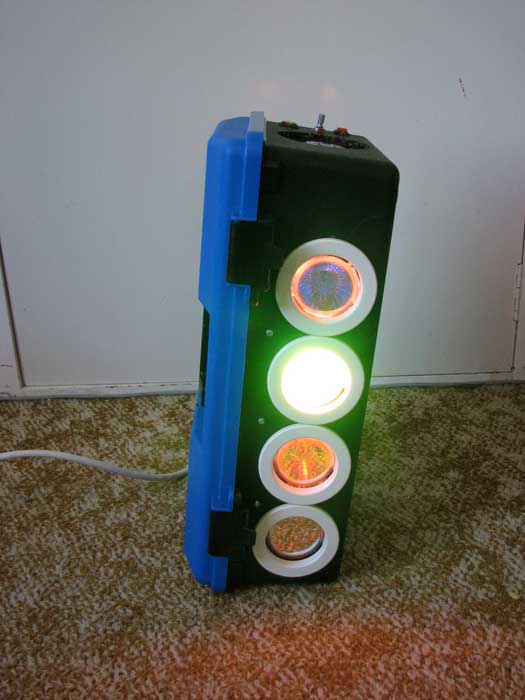
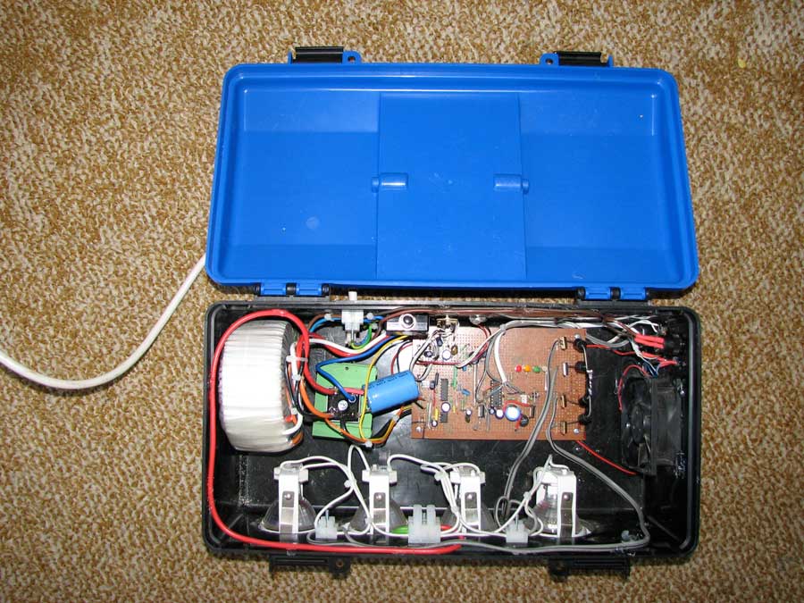
Have fun, I’ve yet to blow a bulb but I suggest you keep a set of replacements as losing one in the middle of a party might be very annoying. Just remember when you change it, they will be hot! Below are pictures of the finished unit and a view of inside the case built on Vero board.
Pictures and videos
Download Picaxe Code
Should you choose to use a PICAXE18A/X, here is the code developed by Hayden Childs that will give you 3 patterns. The terms of use are in comments within the code.
'
''	This code has be tested on the disco lights project at electronics.voltsandbits.com
''	This code may be used and changed or given away as long as the website
''  electronics.voltsandbits.com and the author Hayden E Childs are not edited
''  and a copy of the original code complete with this notice is packaged with it.
''
''
''
''	Author		Hayden E Childs
'	Date Created:	Monday, October 13, 2008, 12:28:35 AM
'	Date Edited	Tuseday, october 26,2008, 13:40:35 PM
'	File Name:	lotsOfpatterns.bas
'	Version:	 1.0
'	Made in New Zealand :)
'

reset: 				'resets pins to 0 or all lights turned off
	low 0
	low 1
	low 2
	low 3
	w4 = 0
					'end reset
main:					'start of the program
	random W0			' makes a random number and stores it in W0 (zero)
	if pin1 = 1 then pickAPat	'waits until it hears a beat (pin 1 = 1 ! 0) b4 picking a random pattern
goto main				'goes back to main


pickAPat:				' pickAPat method allows the program to pick one of the three patterns

	if b1 <63 then blueRule		'goes to blue method if less then 63
	if b1 <126 then chaserPat	'goes to chaserPat if less then 126
	if b1 <255 then rndpat		'goes to rnd Pat if less then 255


goto rndpat				'this is just for the one off chance that it does not get picked up by the test


''blue lights on plz'''''''
blueRule:				'this is the first pattern  that just turns on the green
                        'light (light 3) then when a bet flashs
					'it turns out the green light and tures on the blue light (light 4)
	high 2	'turns pin 2 on
	low 0	'turns pin 0 off
	low 1   'turns pin 1 off
	low 3   'turns pin 3 off
	w1 = 0  'resets random number

	blueStart: 'method
	w4 = w4 + 1 			'adds one to w4
	if w4 = 1000 then reset		'when w4 equals 1000 (how meny times it has run) goes back to reset so a new rnd pattan can be picked

	if pin1 = 1 then greenStart	'what to do when it gets a beat
	goto blueStart

	GreenStart: 'method
	high 3		'turns pin 3 on

	low 2		'turns pin 2 off
	pause 600	'wait 6 sec
	low 3		'turns pin 3 off
	high 2		'turns pin 2 on
	goto blueStart	'go back to start


'''''''''''''''''''''A little chaser pattern''''''''''''''''''''''''''''''''
chaserPat: 'method
w1 = 10		'sets w1 to 10
w2 = 5		'sets w2 to 5 this number is how fast the pattern will change with the number of lights


	CharVarClear:
	if pin1 = 1 then chase  'this method that waits for a beat
	goto CharVarClear

	chase: 		'start of the chase method

	w4 = w4 + 1		'go back to pick a new pattern
	if w4 = 1000 then reset


	low 0				''''''''''''''''''''''
	low 1				'
	low 2				'   this just resets the lights and tells the program to go in reverse
	low 3				'''''''''''''''''
	w1 = w1 + w2 			'adds 5 to w1
	if w1 <10 then chrFlipBack2	'makes the lights go backwards

red:				'method for the red light
	high 0			'turns on first light (red)
	pause w1		' pause as long as w1

	if w1 > 30 then yellow	'when w1 is grater then 30 then starts the yellow method
	                        ' (w1 is how meany time the program runs the pattern)
	goto CharVarClear	'gose back to CharVarClear

yellow:				'yellow
	low 0			'turns off pin 0 (red) turns on pin 1(yellow)
	high 1
	pause w1		'waits w1
	if w1 > 60 then green	'when w1 is greater then 60 then goto green method
	goto CharVarClear	'gose back to CharVarClear

green:				'green method
	low 1			'turns off pin 1(yellow)
	high 2			'turns on pin 2 (green)
	pause w1		'waits w1
	if w1 > 90 then blue 	'when w1 is grater then 90 goto blue
	goto CharVarClear	'otherwise goto CharVarClear

blue:				'blue
	low 2			'turns pin 2 (green) to off
	high 3			'turns on pin 3 (blue) to on
	pause w1		'wait w1 secons
	if w1 > 120 then chrFlipBack1	'when w1 is equale to 120 goto chrflipBack1
	goto CharVarClear

chrFlipBack1:
	w2 = -5			'start to take 5 away from w1 e.g. going backwards
	goto CharVarClear
chrFlipBack2:
	w2 = 5			'start to add 5 to w1 (gose forwaerds)
	goto CharVarClear


'''''''''''first pattern totally random pattern hehehe''''''''''''''''''''''''''''''''''''''''''
rndpat:

		if pin1 = 1 then rndStart 'pattern gose off beat
	goto rndpat


rndStart:

	w4 = w4 + 1 			'adds one to w4
	if w4 = 1000 then reset		'picks a new pattern when it gets to 1000


	low 0	'turns all pins to off
	low 1
	low 2
	low 3

		random W0		'fun random number generated
		if b1 <63 then rndOne	'turns on a random light
		if b1 <127 then rndTwo
		If b1 <186 then rndThree
		if b1 <240 then rndFor


rndOne:
	high 0		'turns on pin 0(red)
	pause 60	'waits 6 sec

goto reset

rndTwo:
	high 1		'turns on pin 1(yellow)
	pause 60	'waits 6 sec
goto reset

rndThree:
	high 2		'turns on pin 2(green)
	pause 60	'waits 6 sec
goto reset

rndFor:
	high 3		'turns on pin 3(blue)
	pause 60	'waits 6 sec
goto reset
''''''''''''end pattern rnd'''''''''''''''''''''''''''''''


'
'	Author		Hayden E Childs
'	Date Created:	Monday, October 13, 2008, 12:28:35 AM
'	Date Edited	Tuseday, october 26,2008, 13:40:35 PM
'	File Name:	lotsOfpatterns.bas
'	Version:	 1.0
'	Made in New Zealand :)
'
''
''	This code has be tested on the disco lights project at electronics.voltsandbits.com
''	This code may be used and changed or given away as long as the website
''  electronics.voltsandbits.com and the author Hayden E Childs are not edited
''  and a copy of the original code complete with this notice is packaged with it.
''
''