This article describes the temperature controlled fan circuit that I designed for my audio amplifier.
The Amplifier
A few years ago I built a new amplifier – the Ultra Low Distortion Amplifier Mk3 by Silicon Chip magazine. It’s an excellent amplifier packing 135W RMS per channel into 8Ω (200W into 4Ω) with barely measurable distortion (claimed 0.004% at 20kHz and even less at 1kHz).
The theoretical efficiency of a class B amplifier is Π/4 or 78.5%. A class AB is somewhat lower than this. Two 200W class AB amplifiers therefore can dissipate in excess of 86W if driven hard. I did not want to have heatsinks protruding outside the rack enclosure like on my previous amplifier (preventing it from ever being able to fit into a rack). To make matters worse, I chose a lower profile 2U rack case than my old amplifier (which was 3U). Such a compact design poses somewhat of a mechanical and thermal challenge.
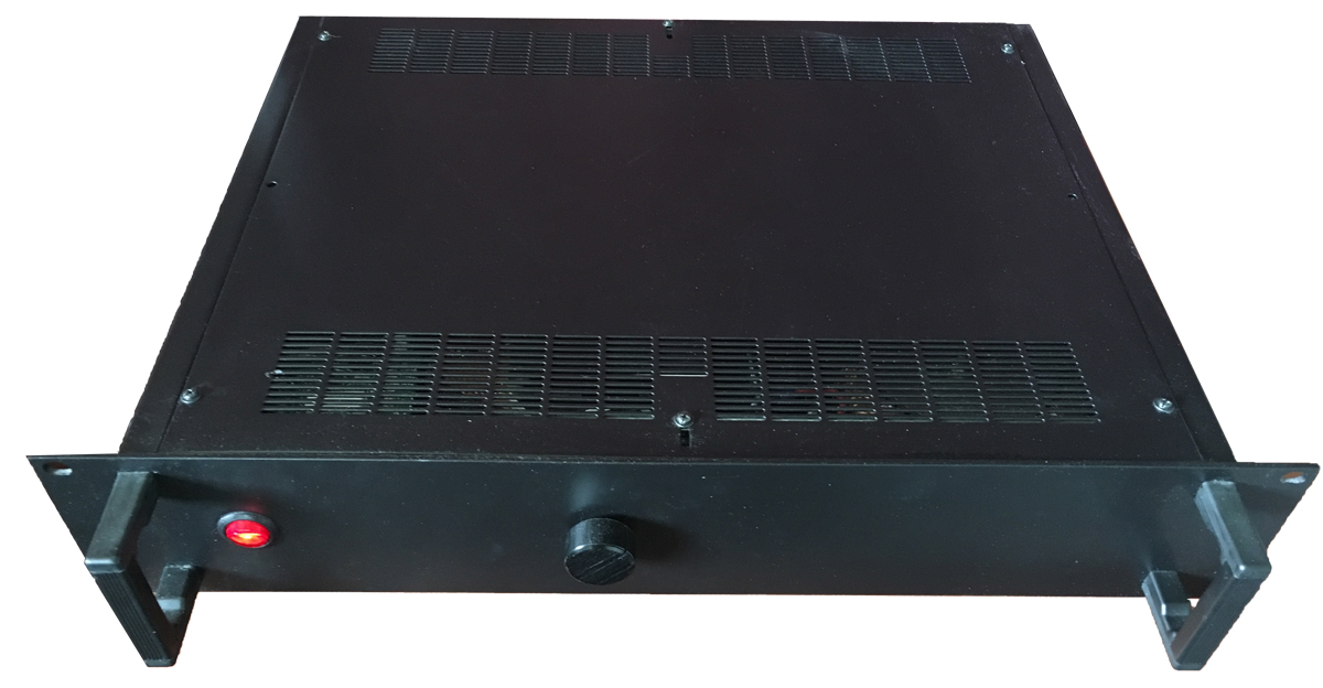
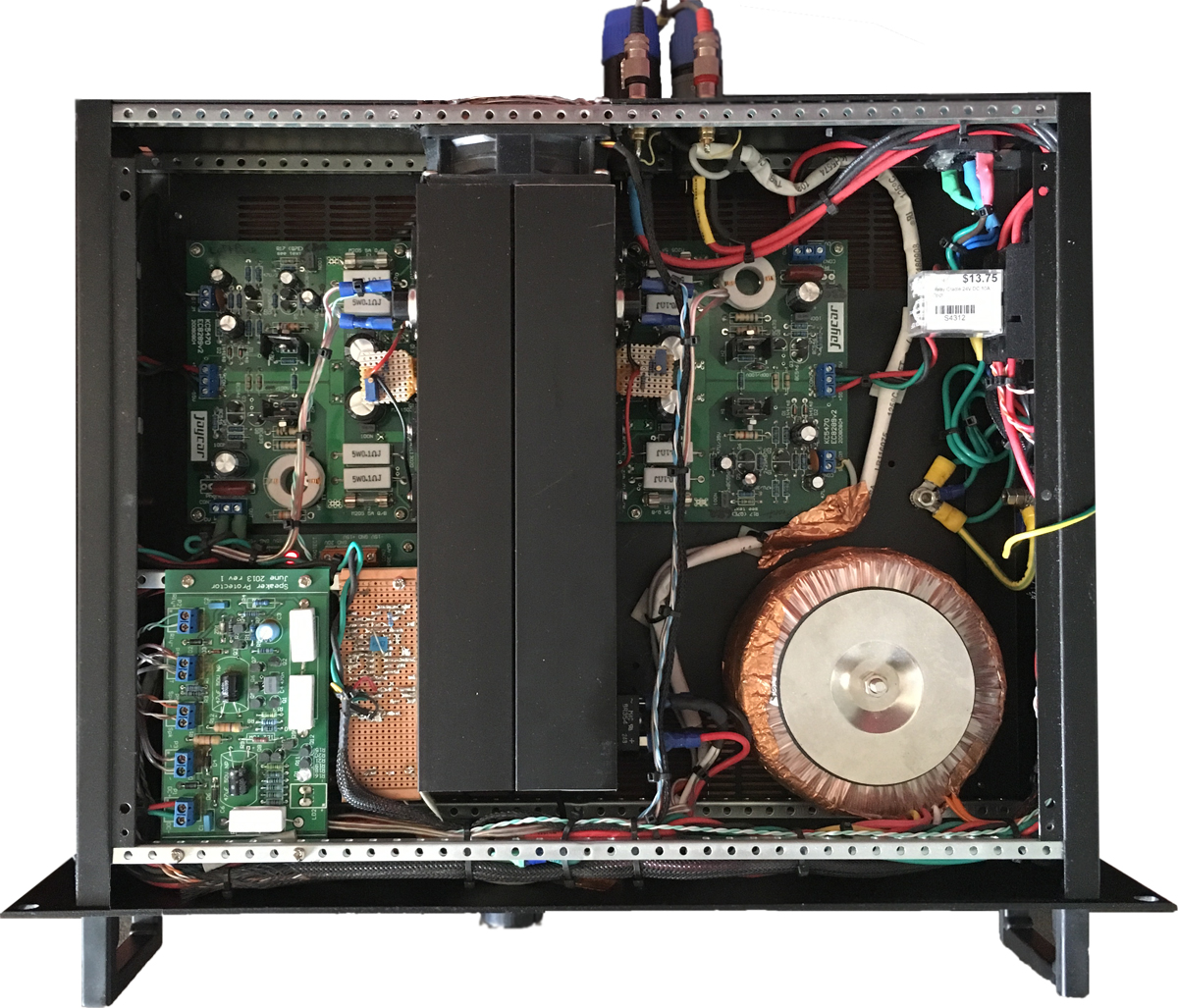
The only reasonable option was to use a fan-forced cooling strategy – tunnel heatsinks down the middle of the chassis with a fan at the back to expel hot air. But with a great amplifier like the Ultra LD Mk3, it would be a shame to add unnecessary fan noise. The answer is to slow the fan right down so that it becomes very quiet and only run it faster if the amplifier is running hot (which likely coincides with loud enough operation that fan noise is not a problem). This article describes a simple analogue temperature controlled fan speed controller. The fan controller was constructed on a piece of Vero board, visible in the lower left of the amplifier.
The fan speed controller
I decided to use a linear power circuit due to extreme need for low electrical noise and the availability of huge heatsinks. This pains me a bit, being an experienced power electronics design engineer. I know that I can design a sufficiently quiet switch-mode converter. A linear design just seemed appropriate in a class AB amplifier. If I build a class D amplifier, I will definitely use a switch-mode design for any controller. Having said that, a class D amplifier would probably be efficient enough to not need a fan at all!
The circuit is shown below. The first thing most people notice is that I have used the negative supply rail. This is because my speaker protection circuit operates only from the positive supply rail, creating a small imbalance in the loading of the supply. It would be trivial to “mirror” the circuit to operate from the positive supply rail instead.
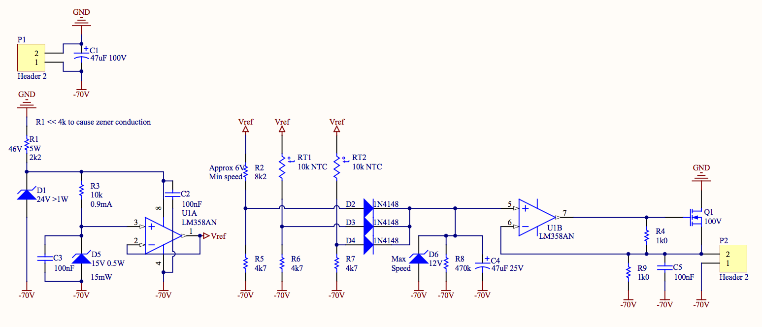
Opamp U1 is powered by a linearly regulated 24V supply rail formed by R1 and D1. A 15V reference is provided by D5 and buffered by U1A. Three DC voltage dividers are then created from this 15V reference. R2 & R5 form a reference level of approximately 6V, which sets the minimum fan speed. (The 12V computer fan that I used was found to start up at about 5V, other fans may be different, so test on a variable supply).
The other two voltage dividers are duplicates of each other, each formed by an NTC and a resistor. (More on the choice of these resistors later). One NTC is bolted to each amplifier heatsink to monitor its temperature. An NTC (negative temperature coefficient) resistor decreases in resistance when it gets hot. Diodes D2, D3 and D4 then select the largest voltage of the three voltage dividers. Zener diode D6 clamps the chosen level to no more than 12V, to avoid overdriving the fan (if the amplifier gets too hot, we still don’t want to apply 70V dc across our fan!) C4 prevents the fan speed from changing too quickly. R8 allows a slow bleed down of C4 (because when the voltage divider voltages decrease, the diodes become reverse biased. Without R8, the fan would never slow down when the amplifier cools down.
The Thevenin equivalent resistance of the voltage dividers is around 1.3kΩ, depending on NTC temperatures. This forms a time constant of about 60ms with capacitor C4 – practically instant. If the amplifier heats up, the fan speeds up, responding very quickly to the NTC temperature to protect the amplifier. If the amplifier cools down, the time constant of R8 & C4 applies. This is around 22 seconds, causing the fan to slow down very gradually. Usually the circuit finds thermal equilibrium fairly quickly (unless the amplifier power dissipation is changing wildly), with no annoying whirring up and down of the fan.
The DC level on C4 is the voltage that I want to have applied to the fan positive terminal (pin2 of header P2). MOSFET Q1 is configured as a source follower, driving the fan. Its gate is controlled by the output of U1B. The source voltage of Q1 (which gets applied to the fan) is fed back to the inverting input of U1B. This allows U1B to compensate for the gate-source voltage drop of Q1 which will vary with the temperature of Q1.
NTC temperature curve
NTCs do not have perfectly linear temperature to resistance curves. Here is a typical 10kΩ NTC curve.
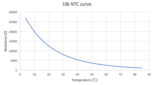
As you can see, the 10kΩ nominal rating is at 25°C. I chose a 4.7kΩ resistor for the bottom of my voltage divider, with a 15V reference voltage. Here is the resulting voltage to temperature characteristic.
![]()
As you can see, the fan runs at its minimum speed until about 33°C. It then speeds up to its maximum speed at about 80°C. The total case to heatsink (including thermal interface material) thermal impedance is about 0.6°/W for each transistor. If each amplifier runs at full power (200W into 4Ω) at a conservative 65% efficiency, each of the four power transistors dissipates 32.5W. With an 80°C heatsink, the junction temperature would be 99.5°C. This is well below the maximum rated junction temperature of 150°C. In fact to reach 150°C, each transistor would need to dissipate 117W steady state, or a total of 467W per amplifier. The power transformer is only rated to 300VA!
I could have made the curve steeper to run the amplifier even cooler, but wanted to minimise fan noise as much as possible. To run cooler, one simply increases the value of R5 and R6.
Howdy! Would you mind if I share your blog with my twitter group? There’s a lot of people that I think would really enjoy your content. Please let me know. Cheers
Certainly, please feel free to tweet about it.